

Difficulty level: Beginner
Approx reading time:
***WARNING: BACKUP SYSTEM PRIOR TO MAKING CHANGES***
Windows Programming:
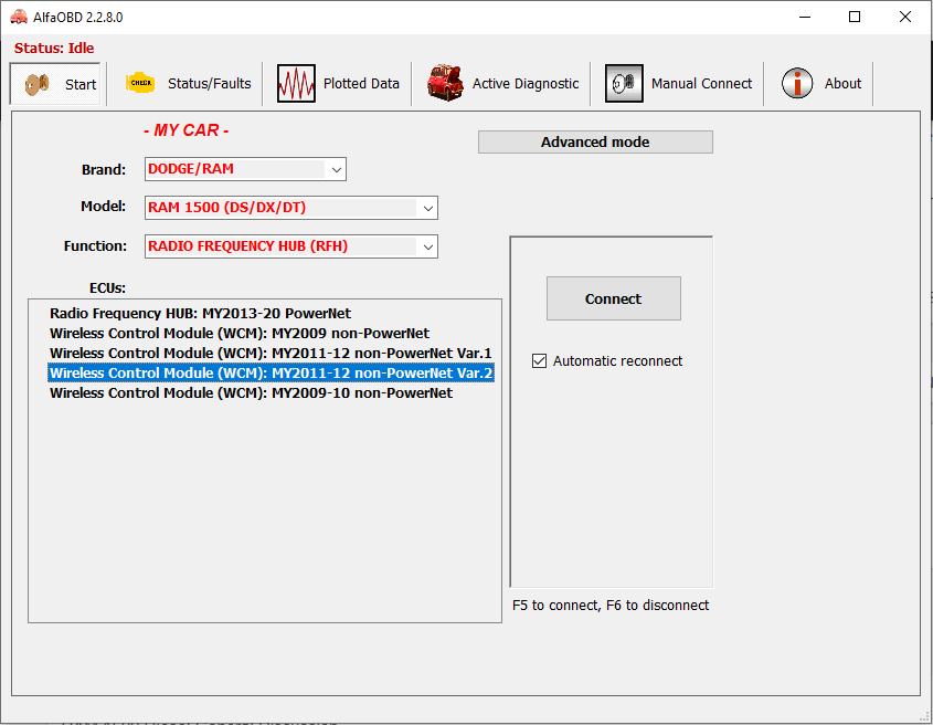
You are going to drill down in the main menu as shown in the image below.
Function: RADIO FREQUENCY HUB (RFH)
Then press Connect
Android Programming:
Rating widget:
AlfaOBD : Backing Up Settings
Difficulty level:
Approx reading time:
Placeholder content coming soon
Rating widget:
AlfaOBD : Getting Connected
Difficulty level:
Approx reading time:
Placeholder content coming soon
Rating widget:
Secure Remote Network Access
Difficulty Level: Intermediate
Reading Time: 15 Minutes
There are several ways to secure a network and allow yourself to have remote access. Some complicated some not so complicated. You can setup port forwarding in your router, but how secure is that?
Here is how I secure my network.
First I use Hamachi from Log Me In
I have a secure network setup and have my devices that support VPN connected. Then due to simplicity, I use my windows 10 machine to forward ports.
This is a simple command-line command using netsh.
netsh interface portproxy add v4tov4 listenaddress=X.X.X.X listenport=9000 connectaddress=Y.Y.Y.Y connectport=8090
Substitute the hamachi address of the windows machine for the X.X.X.X and change the Y.Y.Y.Y to match the local IP address of whatever you are trying to access. For example if the hamachi address of my windows machine was 123.13.121.12 and a local IP camera was sitting on 192.168.1.10 then the command would look like this:
netsh interface portproxy add v4tov4 listenaddress=123.13.121.12 listenport=9000 connectaddress=192.168.1.10 connectport=80
The listenport is what port you will connect to so in this example if I was wanting to look at this webcam from an outside device on my hamachi network I would simply go to HTTP://123.13.121.12:9000. Windows would then forward my connection to the local 192.168.1.10 address on port 80.
With this setup, you can only access my devices from a machine connected to the hamachi network.
Pellet Grill – Getting Started
A lot has changed in the overall way I intend on doing this project. I either currently have or have all of the pieces on order. The parts that I will be using include:
- Raspberry pi 3+ (including SD Card, power supply)
- 4 Channel Relay
- ADS1115 which is a I2C 16 bit analog to digital converter
- Display (Not sure which one I am using yet most likely a 240Hx320W LED)
- VL53L0X which is a time of flight sensor with an I2C interface. (this will aid in monitoring the hopper level)
- HCSR04 Ultrasonic Sensor (Also for hopper level monitoring)
- Various Molex Style Connectors
- Various Resistors
So far the Raspberry Pi has been setup (Tutorial Coming Soon) and ready to go.
Using raspi-config I set enabled I2C and set the hostname (grill)
I changed the I2C Baudrate from the default of 100KHz to 400KHz by adding the following to /boot/config.txt
dtparam=i2c_arm=on,i2c_baudrate=400000
Add the following to the bottom of /boot/config.txt as well:
core_freq=250
I am using piFire software to power this so I am running the installer script from their github.
curl https://raw.githubusercontent.com/nebhead/pifire/main/auto-install/install.sh | bash
This process takes a fair amount of time, more to write when I have time.
Duet : Centering the bed or setting the bed origin
Difficulty Level: Advanced
Reading Time: Minutes
Introduction
With most printer geometries you can choose where on the bed the origin (the X=0 Y=0 point) will be. There are two common choices:
- X=0 Y=0 is at the centre of the printable area. This has a number of benefits. You will configure your slicer to centre prints on X0 Y0 regardless of the size of the bed; so you don’t need to change the slicer configuration depending on the bed size, and you may be able to print the same sliced files on more than one printer. If you have an IDEX printer then you don’t need to change the print centering in the slicer depending on whether you print the part in ditto mode or in normal mode; also IDEX mirror mode printing is easier to set up.
- X=0 Y=0 is one corner of the printable area, typically the front left corner. Some users of Cartesian and CoreXY printers prefer this scheme. You will need to configure your slicer so that it know where the centre of the bed is, in order to centre prints on that position.
Setting the origin on a Cartesian or CoreXY/CoreXZ/CoreXYU printer
The M208 S0 command defines the upper position limits of each axis, and the M208 S1 command defines the lower position limits. When an axis is homed to a low end (minimum) homing switch, the axis is assumed to be at the lower position limit. When it is homed to a high end (maximum) homing switch, it is assumed to be at the upper position limit. Therefore, changing the position limits in the M208 command will move the origin.
Example: a Cartesian printer uses a low end X homing switch, which triggers when the head reference point (i.e. the nozzle in a single tool printer) is 8mm off the low-X edge of the bed. It uses a high-end Y homing switch, which triggers when the head reference point is 2mm off the high-Y edge of the bed. The bed is 200mm square.
1. Suppose we want to make X0 Y0 the centre of the bed. Then the Xmin edge of the bed is at X=-100 and the homing switch triggers at X=(-100-8) = -108mm. Similarly, the Ymax edge of the bed is at Y=100 and the Y homing switch triggers at Y=(100+2) = 102mm. So we can use the following commands in config.g:
M208 S0 X-108 Y-100  ; set axis lower limits
M208 S1 X100 Y102    ; set axis upper limits
or alternatively when using firmware 2.02 or later:
M208 X-108:100 Y-100:102 ; set axis limits
2. If instead we want to make X0 Y0 the corner of the bed then we would use:
M208 S0 X-8 Y0     ; set axis lower limits
M208 S1 X200 Y202  ; set axis upper limits
or if using firmware 2.02 or later:
M208 X-8:200 Y0:202 ; set axis limits
Notes:
1. You would normally have Z parameters in the M208 commands too.
2. The M208 limits set the position immediately after the corresponding G1 S1 command completes by triggering the homing switch. However, if your homing file has a G92 command after the G1 S1 command (as is typically the case when homing to a Z-min switch), then the G92 command will override that position.
Duet : Calibrating Z Probe
Difficulty Level: Advanced
Reading Time: Minutes
Test and calibrate a Z probe
Static test of the Z probe
Static test using the web interface
- Apply power to the printer.
- Connect to the printer from a browser.
- If the probe needs to be deployed before use (e.g. BLTouch), test the deploy and retract functions, by sending M401 to deploy the probe and M402 to retract it.
- With the Z probe deployed (if applicable) but not close enough to the bed to trigger it, check that the Z probe reading in Duet Web Control is zero or close to zero.
- If your Z probe is of a type that produces a continuous output when triggered (for example IR, inductive, capacitive and switch-type probes), hold a surface below the Z probe to cause it to trigger (or jog the nozzle towards the bed until it is close enough to trigger). Check that the Z probe reading in DWC is correct (about 537 for the Mini Differential IR probe, and about 1000 for most other types).
- If your Z probe produces a short pulse when it triggers (e.g. Smart Effector, Precision Piezo, FSRs with John SL board, BLTouch) then the pulse will probably be too short for you to see. Proceed to the dynamic test.
Static test using Panel Due or a USB connection
As above, but either monitor the Z probe reading in PanelDue if you have one, or send G31 via USB every time you want to read it.
Dynamic test
- Apply power to the printer.
- Connect to the printer from a browser or via USB.
- If your printer is Cartesian or CoreXY, home X and Y. If it is a Delta, home all.
- Position the print head well above the bed.
- Send command G30 to do a single Z probe. This will deploy the probe (if applicable) and start the head descending or the bed rising.
- Hold a suitable surface below the print head to trigger the Z probe. The probe should trigger and the Z movement should stop.
- If the Z movement doesn’t stop, turn off power to the printer before the head crashes into the bed. It is also a good idea to reduce motor currents in case of a crash.
Calibrate the Z probe trigger height
- Make sure the dynamic test is successful (Z probe stops when it senses the bed) before doing this.
- Cancel any currently active mesh compensation with M561
- Use the X and Y jog buttons to position the nozzle over the centre of the bed
- Jog the nozzle down until it is just touching the bed or just gripping a sheet of paper. If the firmware doesn’t let you jog it down far enough, send M564 S0 to disable axis limits.
- Once you have the nozzle touching the bed, send command G92 Z0 to tell the firmware that the head is at Z=0
- Jog the head up by 5 to 10mm
- Send command G30 S-1. The nozzle will descend or the bed rise until the probe triggers and the Z height at which the probe stopped will be reported. If you are using a nozzle-contact Z probe, the trigger height will be slightly negative. For any other type of Z probe where the probe triggers before the nozzle contacts the bed, it will be positive.
- Repeat from step 5 two or three times to make sure that the trigger height is consistent.
- In Duet Web Control, go to Settings -> System Editor and edit the config.g file. Set the Z parameter in the G31 command to the trigger height that was reported. Save the file.
- Open config-override.g and check that there are no G31 commands in it. If you find any, delete those lines and save the file.
- To apply the new trigger height, restart the Duet by sending M999 or pressing Emergency Stop.
Fine tuning the trigger height
After you’ve done the procedure above, you can fine tune your G31 Z value to get a good first layer. During a test print, watch the first layer go down and adjust the Z position using the baby stepping function. If you have to move the nozzle closer to the bed, increase the G31 Z value by the amount of baby stepping used. If you have to move the nozzle farther away from the bed, decrease the G31 Z value by the amount of baby stepping used.
Measuring Probe X Y Offset
- The firmware needs to know the position of the probe in relation to the tool. In most cases, the nozzle tip.
- If your probe uses the nozzle tip, the X Y offset would be G31 X0 Y0.
- If you have access to the CAD files for your probe mount you may already know the probe X Y offset, or it may have been provided to you with the parts.
- Otherwise, you will need to measure the distance between probe and nozzle.
Here is an easy way to measure the offset:
- Tape down a piece of paper onto the bed.
- Bring the nozzle down to the bed surface and lower it until the nozzle starts to depress into the paper, making a small impression.
- Mark the impression with a marker tip to make it more visible.
- Now jog X and Y until the probe is directly over the spot where the nozzle was.
- Take the amount you jogged as your X and Y offset to use in G31.
- When the probe is to the left of the nozzle the X value is negative.
- When the probe is in front of nozzle the Y value is negative.
- To the right and behind the values are positive.
Note that the offsets will follow the right hand coordinate system, meaning that X movement to the left of the nozzle will be negative, and right of the nozzle will be positive. And Y movement behind the nozzle will be positive, and movement in front of the nozzle will be negative.
Here’s an example of how to measure.
More information on Z Probes
- Help with Choosing a Z probe
- Information on Connecting a Z probe
BL Touch
There is detailed information here:
Also BeTrue3d.dk has a very detailed tutorial on using a BL touch, including how to setup bed leveling an bed compensation here:
Ambilight
Difficulty Level: Advanced
Reading Time: Minutes
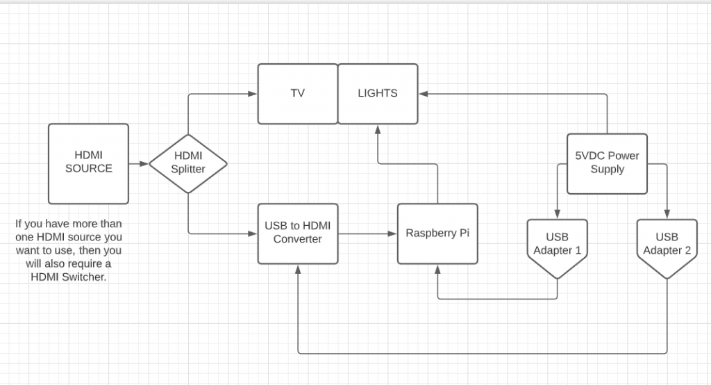
Let’s begin with the required parts.
Hardware:
- Raspberry Pi 3 Model B
- You may want a case, I used this: Argon Fan Hat
- SD Card 8GB should be plenty
- HDMI Splitter
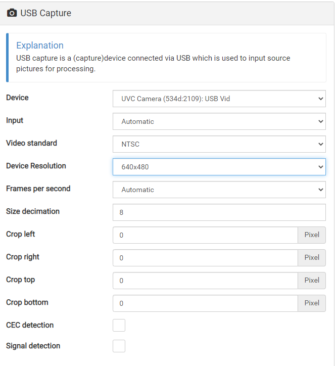
- USB HDMI Video Capture
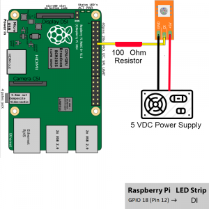
- 100 Ohm Resistor
- WS2812B LED Strip
- USB Breakout Block
- 5 Volt Switching Power Supply (Make sure enough wattage for your LEDs Read Here for more info.)
Software:
 Only thing remaining is powering the Pi, and Splitter. You can do this anyway you want, you may power the splitter off of the Pi and then use a good quality power supply for the Pi. I used USB terminal block as shown here.
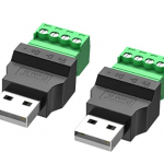 Only the outside two terminals need wired the one on the left looking at it (Pin 4) is your ground from the power supply, and the one on the right (Pin 1) is the +5vdc from the power supply. I put two of these in and plugged everything to them.
No joy…..
Well today, I plugged in my completed BIAS lighting system in, I had image on the TV so I knew the splitter was working just fine. However, I was getting nothing on the LEDS at all. I checked the voltage levels and had good voltage everywhere. Check continuity from the Arduino to the led light strip and there were no issues. I scratched my head and looked over my wiring again and determined I had the LED data plugged in to the wrong GPIO port on the Arduino. I changed it and viola we had one single light flashing white. The very first light in the chain flashed white nonstop while nothing else did anything.
I went over the settings checked everything several times…. and could not find anything wrong.. The only way to really test the Arduino is to plug directly into it from the computer, which is a bloody nightmare with how everything is setup. So this made me think, why do I need the Arduino anyway? I can control the lights from the raspberry pi, so that is what I will be doing trying to control it from the Pi, and see what we get. The only other thing I can possibly think of is that the Raspberry Pi, is not handling the digital signal input properly.